
In the last five years or so, you’ve probably come across a new and exciting technology known as “3D printing.” It might surprise you to learn that 3D printing has existed in some form for around 30 years. Beginning in 2002, some of the earliest 3D printing patents began to expire. With the expiration of these patents and advances in the production of low-cost, easily programmed microcontrollers, 3D printing has exploded in popularity. Hopefully, this article will give you a glimpse of how this exciting technology can add a new “dimension” to our civil engineering designs and provide additional value to our clients and communities.
What is “3D Printing”?
3D Printing is a form of additive manufacturing where a three-dimensional object is built up one thin layer at a time. Many different processes and technologies for 3D printing exist. These processes are defined in ISO/ASTM 52900, but some of the most common include:
- Material Extrusion (Fused Deposition Modelling (FDM)): Material is selectively dispensed through a nozzle or orifice.
- Vat Polymerization (SLA and DLP): Liquid photopolymer in a vat is selectively cured by UV light
- Powder Bed Fusion (SLS, DMLS and SLM): A high-energy source selectively fuses powder particles.1
The most commonly available “consumer” 3D printer models are material extrusion models. If you’ve never seen one of these machines in action, picture a hot glue gun mounted on an old pen plotter. Now imagine that the glue gun “pen” (extruder) draws an object layer by squirting glue onto the paper (build surface). When one layer is drawn, the pen raises up (or paper lowers down) by the thickness of one layer and begins drawing another layer on top of the previous layer. The printer then repeats this process until all the object’s layers have been drawn, resulting in a 3D object. A simple search for “3D printing time-lapse” will reveal hundreds of videos illustrating the process. Here are a couple of videos:
- 3D printed Eiffel tower time lapse 2
- Baby Groot – 3D Printing Time Lapse3
3D CAD Revolution
Along with the explosion in 3D printing, the last 10 to 15 years have seen significant advances in the realm of computer-aided design (CAD). With CAD software tools like Autodesk’s Civil 3D and Revit and Bentley’s InRoads and OpenRoads Designer, our industry has seen an increasing shift to 3D design for buildings, roadways, bridges, pipe networks, earthworks and more. It’s not hard to imagine a future where two-dimensional plan sheets — paper or electronic — are obsolete and replaced with 3D interactive models of our designs. In fact, there are organizations such as the Utah Department of Transportation (UDOT) that are actively pursuing initiatives to transition away from 2D deliverables such as paper plan sets. See UDOT’s Digital Delivery Website4 or refer to UDOT’s March 2017 Intelligent Design and Construction Guidance document.5
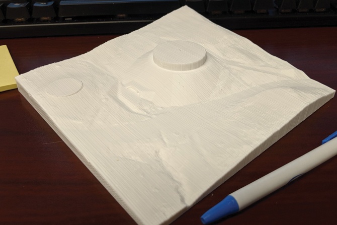
It is one thing to show clients or the public a realistic 3D rendering of your latest design in a video clip or simulation. However, sometimes it helps to sit around a table and point to a physical plan or model to collaborate effectively and communicate design intent or potential concerns. Relatively easily, we can now combine our 3D CAD designs with 3D printing to produce physical models.
From 3D CAD to 3D Print
Your CAD software handles the conversion from CAD format to a printer spool file that your inkjet or laser printer can print. However, most currently available 3D printers and 3D printing service providers require you to convert a 3D model to a specific type of file called a Stereolithography (STL) file. The STL file is currently the 3D printing industry standard for distributing 3D printable files. 3D Printers and printing service providers take the STL file and run the file through a “slicing” process where the model is broken down into the individual layers that will be printed and combined into the final 3D print.
Because every printer handles the actual slicing process slightly differently, we will limit our discussion to how to create an STL file from a 3D CAD model. Also, while several CAD software packages can generate 3D designs, we will focus on using Civil 3D. It is currently the most popular civil design CAD software on the market.
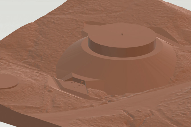
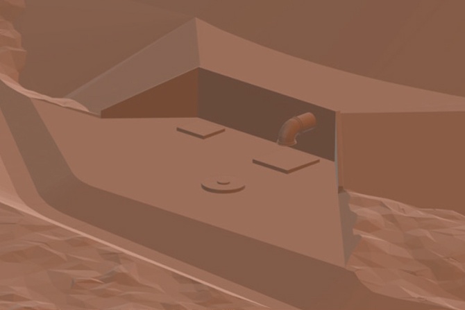
The image below is an STL file created from a concrete water tank design consisting of a finished grade surface, a 3D model of the tank, and the associated tank and storm drain pipe networks.
The creation of the Civil 3D objects that make up the design pictured above is beyond this article’s scope. However, the commands described below can convert Civil 3D objects into a single, 3D printable STL file.
Export Surface to Solid.
Entering EXPORTSURFACETOSOLID in the command line will bring up the following dialog:
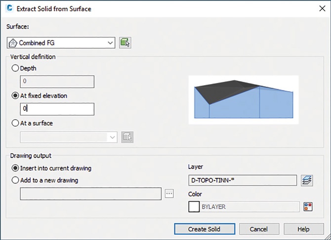
Select the TIN surface you want to export from the dropdown box. In the “Vertical definition” section, select “At a fixed elevation” and specify an elevation just below the minimum elevation of your selected surface. This selection will give your surface a thickness and a flat bottom at the elevation you specify, which is great for providing a solid first layer to your 3D print. Review the drawing output section, accept the default values or change as necessary for your needs. When you hit the Create Solid button, Civil 3D will create a solid model of your TIN surface. If your TIN surface is too dense (which is common when using LiDAR-derived terrain surfaces), you may need to use the SIMPLIFYSURFACE command to reduce the number of points in your TIN before you export the surface.
Civil 3D pressure and gravity pipe networks contain all the information needed to create 3D models of pipes and structures by default, but you need to use the CONVERTO3DSOLIDS command to create solid objects that you can export for 3D printing. If you start the command from a plan view orientation, you will get a warning recommending that you switch to a 3D view. If you get this warning, cancel, use ORBIT to rotate your view slightly and start the CONVERTOT3DSOLIDS command again. Now select the pipes and structures you want to export and hit enter. Choose whether you want to delete your existing pipes and structures (probably not, as this would break the annotation labels, styles, and profiles associated with those pipes and structures) and hit enter again. The result of this command should be individual “3D solid” objects representing your pipes and structures.
Create Other 3D Solid Objects as Needed
Civil 3D includes all the advanced 3D CAD commands necessary to create primitive 3D solids such as cubes, spheres, cylinders, cones, etc. You can use these commands to create basic representations of tanks, buildings and other features you might need to be included in your 3D print. For more complex 3D objects, research the EXTRUDE, LOFT, SWEEP, REVOLVE, and PRESSPULL commands. The large tank in Figure 1 was created by tracing a structural section view outline and using the REVOLVE command.
Combine all 3D Solids and Export STL File
Once you have all individual design elements converted to “3D solid” object types, use the UNION command to combine the separate entities into a single object. When complete, use the STLOUT command and select your single 3D solid object. You will be asked if you want to create a binary STL file. You can enter yes or no; both will result in a 3D printable STL file.
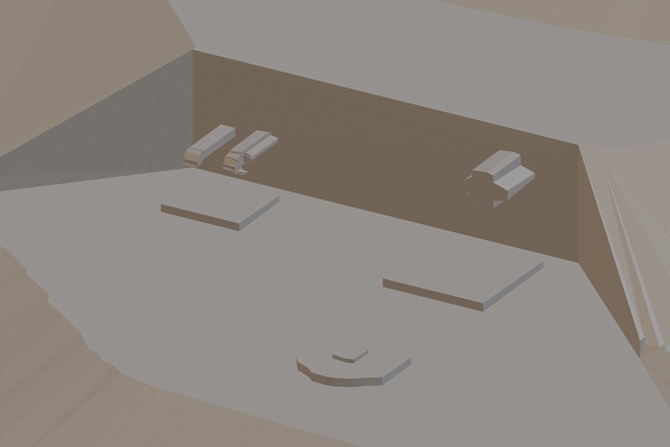
I have one note of caution with the STLOUT command. There is a software bug that sometimes affects models that are exported from their true world coordinates. If the resulting STL file appears to have lost a significant amount of resolution and appears “blocky” as in Figure 4 below, try moving the solid object in Civil 3D to the drawing file’s global origin (i.e., coordinates 0,0,0) and executing the STLOUT command again.
- Creality Ender 3 (about $200)6
- Prusa i3 MK3S (about $1,000)7
- Ultimachine Ultimaker S5 (about $6,000)8
- 3D Hubs9
- Shapeways10
- Sculpteo11
Further Reading
For additional details about 3D printing and associated best practices, I highly recommend reading the 3D printing guide on the 3D Hubs website.12
Feel free to contact me with additional questions at cmerrell@bowencollins.com.
References
- From https://www.3dhubs.com/guides/3d-printing.
- 3D printed Eiffel tower time lapse: https://www.youtube.com/watch?v=FqQAjkZOBeY
- Baby Groot: https://www.youtube.com/watch?v=m_QhY1aABsE
- UDOT Digital Delivery Website: https://digitaldelivery.udot.utah.gov/
- UDOT March 2017: https://drive.google.com/file/d/1wvmo_0lAY6yeWyLcYsFmKCFEpYPah3Ar/view
- Creality Ender 3: https://www.creality3dofficial.com/products/official-creality-ender-3-3d-printer
- Prusa i3 MK3S: https://shop.prusa3d.com/en/3d-printers/181-original-prusa-i3-mk3s-3d-printer.html
- Ultimachine Ultimaker S5: https://www.matterhackers.com/store/l/ultimaker-s5/sk/MH6DVDNK
- 3D Hubs: https://www.3dhubs.com/
- Shapeways: https://www.shapeways.com/
- Sculpteo: https://www.sculpteo.com/en/
- Visit www.3dhubs.com/guides/3d-printing/.
Clint Merrell
Clint attended Brigham Young University and graduated with a Master of Science in Civil and Environmental Engineering, emphasizing water resources, in 2009. Since then, he has worked throughout Utah, Colorado, and California on a variety of heavy civil projects, including roadways, railroads, storm drain systems, water distribution systems, and large flood control structures. Clint is currently a project manager and associate at Bowen Collins and Associates. He lives in St. George, Utah, with his wife, Jessica, and their three children.