

In the U.S., buildings have an average life span of 70-75 years (DOE, 2011) and represent 40% of the country’s annual energy use (Energy Information Administration, 2012). Consequently, design choices related to new buildings have a significant and long-lasting impact. In general, it is important to consider energy consumption and cost for the design of every building. However, when buildings are part of a larger campus, a single-building perspective can fall short of identifying how the buildings can interact to reduce their overall energy consumption, cost or emissions. This reduction is only achievable through a multibuilding analysis simulation. One difficulty of performing a multibuilding simulation is that each building is probably only defined conceptually during the early design phase of a large campus. This article will go through one way to simulate, analyze and optimize the mechanical system types for a campus when only building function type, quantities of buildings, and size is known.
A good starting point, and excellent overall resource, for modeling building energy consumption from a high-level perspective are the DOE Prototype Building models (Commercial Prototype Building Models, 2021) created by researchers at Pacific Northwest National Laboratory (PNNL). There are 16 commercial building types available for 19 different climate locations that represent 75% of the commercial building stock in the U.S. The prototypes were created using data from the Commercial Buildings Energy Consumption Survey (CBECS, 2015), which in 2003 included data from 5,215 buildings. The CBECS database is thorough and includes information such as floor area, occupancy, and envelope construction. For information not readily available in the CBECS survey, the PNNL prototype buildings use guidelines outlined in ASHRAE 90.1 for criteria such as operating schedules, infiltration, and lighting power densities. The prototypes are available for efficiency requirements outlined in ASHRAE 90.1 and the International Energy Conservation Code from 2004 through 2019. These prototypes are specifically designed for use with EnergyPlus, a building energy analysis and thermal load simulation program developed by the Department of Energy. EnergyPlus is free to download and use. It may be accessed here: https://www.energy.gov/eere/buildings/downloads/energyplus-0.
Even though these prototype models won’t be an exact match for every project, they are a very useful template. They can be used as a consistent starting point for evaluating design choices such as the HVAC system type. For example, consider a project where a developer would like to construct a six-office building campus. They intend to have two 580,000 square-foot, 14-story office buildings with data centers and four 110,000 square-foot, 6-story office buildings. Countless possibilities can be considered, but for the sake of this exercise, the following options will be evaluated: typical HVAC systems, all-electric HVAC systems, a blend of any system, and then a central plant that services the entire campus. The central plant’s underlying purpose is to capture the waste heat from the data centers to heat office spaces in the winter.
The overall procedures for evaluating these different scenarios are listed below:
- Review the DOE building prototype database and select buildings of similar functional use.
- Select the building template file for the correct code version and correct climate zone and download the appropriate TMY3 (Typical Meteorological Year) weather file.
- Adjust room multipliers and floors to align the template building file with the campus’s proposed functional usage.
- Modify and/or add HVAC systems to align with the different mechanical systems considered in the assessment.
- Run the simulations and normalize energy use and emissions on a square foot basis.
- Evaluate the solution set to select the system types that best align with the project objectives.
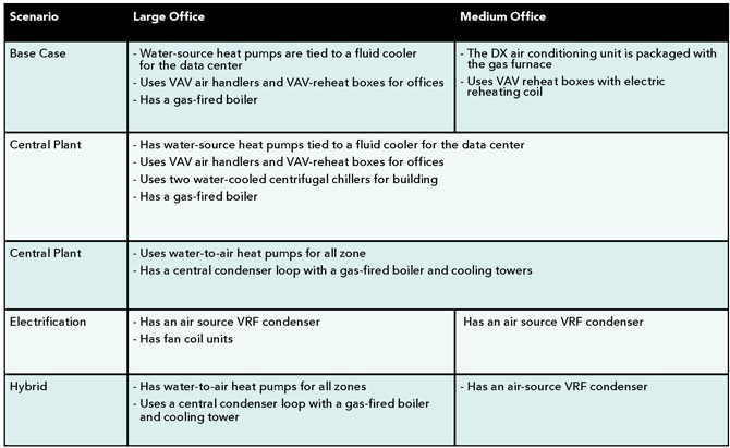
The template files can be simulated without modification to evaluate the base case. The large office and medium office HVAC systems are changed to air-source VRF to evaluate the electrification scenario. Lastly, the large-office template is modified for the central plant scenario so that the ratio of office space and data center square footage is equivalent to the total ratio of the eight buildings. This modification is done by adjusting the number of occurrences for each zone or adding floors to the buildings. Lastly, the HVAC system type is changed to water-to-air heat pumps with a central condensing loop.
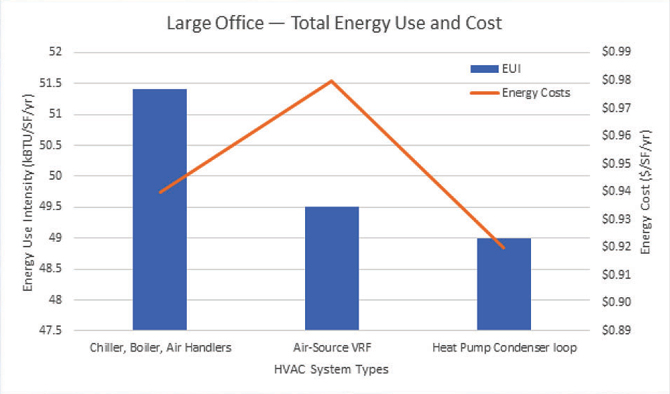
Building simulation results (see Figure 1) show that for the large office, the traditional HVAC system, or base case, has a higher energy use intensity (EUI) compared to either of the alternative system types. It is interesting to note that for the large office, an Air-Source VRF system has a lower EUI, but the annual operating cost is higher. The higher operating cost is due to wintertime electricity charges for running the VRF system in heating mode and the reduced efficiency with using Air-Source VRF to cool the data center compared to heat pumps tied to a fluid cooler. The lowest EUI and operating cost system for the Large Office is the heat pump system.
A water-to-air heat pump system is well suited for large offices in the Salt Lake City climate because the data center’s waste heat can be recovered and used to heat office spaces. Furthermore, when the heat from the data center is insufficient to heat the entire building, the central boiler can operate in the condensing mode since the return water temperature is much lower for a heat pump condensing loop than a standard heating water system. Finally, the heat pump system has a lower EUI than the air-source VRF because the cooling tower rejects heat at the wet-bulb temperature, whereas the air-source VRF system rejects heat at the dry-bulb temperature. In the Salt Lake climate, the wet-bulb temperature is significantly lower for the majority of the year.
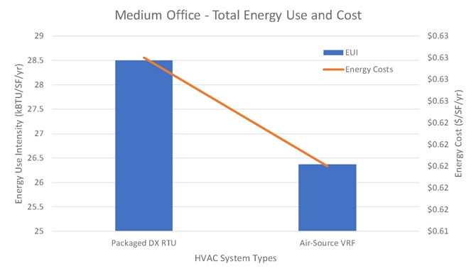
In contrast, the medium office is best served by an air-source VRF system, as shown in Figure 2. The VRF system allows for load sharing between different spaces and is more efficient with a smaller EUI than the packaged DX rooftop unit with a gas furnace. Given that the medium office has a much lighter heating and cooling load than the large office, the VRF system doesn’t cause significant electrical demand charges, reducing the annual operating cost compared to the VRF system serving the large offices.
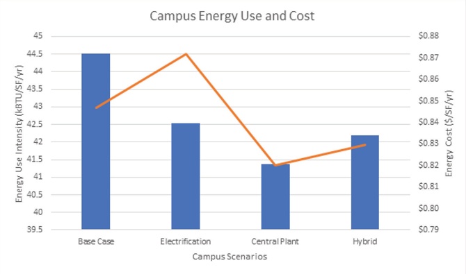
When viewed as a wholistic campus, the base case scenario has the worst EUI and operating costs, followed by the electrification scenario and, finally, the hybrid scenario. (Figure 3) By far, the best performing system type for the campus is a central plant because the waste heat from the data centers can be recovered and reused throughout the campus. Furthermore, the water-to-air heat pumps have a higher efficiency than air-source VRF because the condenser loop is maintained at a moderate temperature year-round.
This article describes a high-level energy modeling technique for evaluating campus buildings during the early design phase. Utilizing the PNNL template files makes it possible to quickly evaluate different HVAC systems for multiple buildings in an office campus. This approach can be beneficial during the design phase because it makes it possible to simulate different building types without creating full building energy models from scratch. Additionally, it is possible to simulate multiple buildings from a campus-level perspective to see if there are opportunities to reduce energy consumption and cost by interconnecting buildings with complimentary load profiles. It is important to note that this high-level approach is best suited for eliminating design choices early on. If different scenarios have relatively similar EUIs or operating costs, then detailed energy modeling should be conducted once the project is more fully defined.
References
- DoE, U. S. (2011). Buildings energy data book. Energy Efficiency and Renewable Energy Department, 286.
- Energy Information Administration (U.S.) (Ed.). (2012). Annual Energy Outlook 2012: With Projections to 2035. Government Printing Office.
- Commercial Prototype Building Models. (n.d.). Retrieved January 31, 2021, from https://www.energycodes.gov/development/commercial/prototype_models
- CBECS (2015). Commercial buildings energy consumption survey (CBECS). U.S. Department of Energy: Washington, D.C., USA.
Gabriel Legorburu, P.E., Ph.D.
Gabriel Legorburu specializes in energy modeling, optimization and mechanical design for Industrial facilities and campuses. He is enthusiastic about designing robust, cost-effective, and efficient mechanical systems that meet client expectations. He is currently a senior mechanical engineer and mechanical team leader at Food Tech, a nationally recognized design builder that constructs food and beverage companies’ facilities.
Gabriel has worked in the construction industry for 17 years and currently holds licenses in states across the U.S. He received his Ph.D. in Mechanical Engineering from the University of Utah, a master’s in Mechanical Engineering from Ohio University, and a bachelor’s degree from the University of Nevada, Reno.